Table of Contents
ToggleAcomparatoris an electronic circuit, which compares the two inputs that are applied to it and produces an output. The output value of the comparator indicates which of the inputs is greater or lesser. Comparator using op-amp is discussed in the following section.
Op-Amp as Comparator
Comparator is nothing but an open loop op-amp, with two inputs and one output. It compares a signal voltage applied to one input to op-amp, with known voltage applied to other input.
The output of comparator is either positive saturation or negative saturation, depending on which input is larger. It has following types,
- Inverting Comparator
- Non-Inverting Comparator
Inverting Comparator using Op-Amp
In inverting comparator, the input signal is applied at the inverting terminal and reference voltage is applied at non-inverting terminal of Op-amp.
It is divided into two types depending on reference voltage applied to it.
- Inverting Comparator with positive reference voltage
- Inverting Comparator with negative reference voltage
Inverting Comparator with Positive Reference Voltage
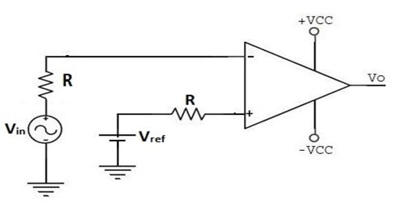
It is the comparator in which input is applied to inverting terminal and reference voltage is applied to non-inverting terminal. Reference voltage applied is positive. It is shown in the following figure.

Circuit Operation
When Vin is less than Vref , the voltage at non-inverting terminal is greater than voltage at inverting terminal. This makes the differential voltage Vid positive and hence output will be in positive saturation (+Vsat).
When Vin is greater than Vref , the voltage at inverting terminal is greater than voltage at non-inverting terminal. This makes the differential voltage Vid negative and hence output will be in negative saturation(-Vsat).
Input-Output waveform
The output waveform of Inverting Comparator with positive reference voltage is shown in following figure.

Inverting Comparator with negative reference voltage
It is the comparator in which input is applied to inverting terminal and reference voltage is applied to non-inverting terminal. Reference voltage applied is negative. It is shown in the following figure.

Circuit Operation
When Vin is less than Vref , the voltage at non-inverting terminal is greater than voltage at inverting terminal. This makes the differential voltage Vid positive and hence output will be in positive saturation (+Vsat).
When Vin is greater than Vref , the voltage at inverting terminal is greater than voltage at non-inverting terminal. This makes the differential voltage Vid negative and hence output will be in negative saturation(-Vsat).
Input-Output waveform
The output waveform of Inverting Comparator with negative reference voltage is shown in following figure.

Video Tutorial on Inverting Comparator
Non-Inverting Comparator using Op-Amp
In non-inverting comparator, the input signal is applied at the non-inverting terminal and reference voltage is applied at inverting terminal of Op-amp.
It is divided into two types depending on reference voltage applied to it.
- Non-Inverting Comparator with positive reference voltage
- Non-Inverting Comparator with negative reference voltage
Non-Inverting Comparator with positive reference voltage
It is the comparator in which input is applied to non-inverting terminal and reference voltage is applied to inverting terminal. Reference voltage applied is positive. It is shown in the following figure.

Circuit Operation
When Vin is less than Vref , the voltage at non-inverting terminal is less than voltage at inverting terminal. This makes the differential voltage Vid negative and hence output will be in negative saturation (-Vsat).
When Vin is greater than Vref , the voltage at non-inverting terminal is greater than voltage at inverting terminal. This makes the differential voltage Vid positive and hence output will be in positive saturation(+Vsat).
Input-Output waveform
The output waveform of Non-Inverting Comparator with positive reference voltage is shown in following figure.

Non-Inverting Comparator with negative reference voltage
It is the comparator in which input is applied to non-inverting terminal and reference voltage is applied to inverting terminal. Reference voltage applied is negative. It is shown in the following figure.
Circuit Operation
When Vin is less than Vref , the voltage at non-inverting terminal is less than voltage at inverting terminal. This makes the differential voltage Vid negative and hence output will be in negative saturation (-Vsat).
When Vin is greater than Vref , the voltage at non-inverting terminal is greater than voltage at inverting terminal. This makes the differential voltage Vid positive and hence output will be in positive saturation (+Vsat).
Input-Output waveform
The output waveform of Non-Inverting Comparator with negative reference voltage is shown in following figure.

Video Tutorial on Non-inverting Comparator
For Video Tutorial on Inverting Comparator in Hindi
For Video Tutorial on Non-inverting Comparator in Hindi
Recent posts
Related posts:
- Introduction to Op-amp
- Parameters of Op-amp
- Configuration of Op-Amp
- Open Loop Configuration of Op-Amp
- Closed Loop Configuration of Op-Amp
- Virtual Short and Virtual Ground Concept
- Summing Amplifier Using Op-Amp | Adder Using Op-Amp
- Difference Amplifier Using Op-Amp | Subtractor Using Op-Amp
- Integrator Using Op-Amp
- Differentiator Using Op-Amp
- Zero Crossing Detector (ZCD)


Hi electronicsforyou.in admin, Thanks for the well-structured and well-presented post!
Everything is very open with a clear clarification of the challenges. It was truly informative. Your site is extremely helpful. Thanks for sharing!